


Place the aggregator inside the machine’s power panel (or outside panel if using an external sensor).

If an existing aggregator is installed: Connect the new aggregator via CAT5 cable to the existing device's second CAT5 jack.
If there is no existing device: Connect the aggregator to the gateway via CAT5 cable using either CAT5 jack.

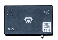
Check for a solid blue LED light in the lower left corner of the digital aggregator.
This indicates power and successful gateway connection.


Place the aggregator inside the machine’s power panel (or outside panel if using an external sensor).
If an existing aggregator is installed: Connect the new aggregator via CAT5 cable to the existing device's second CAT5 jack.
If there is no existing device: Connect the aggregator to the gateway via CAT5 cable using either jack.
Check for a solid blue LED light in the lower left corner of the digital aggregator.
This indicates power and successful gateway connection.
First you must identify which signal you will be working with. Then, you’ll locate that signal in your machine’s power panel and identify the nearest power outputs.
It’s critical to choose a signal that changes back and forth exactly once per cycle.
Place the aggregator inside the machine’s power panel (or outside panel if using an external sensor).
Check for a solid blue LED light in the lower left corner of the digital aggregator.
This indicates power and successful gateway connection.
How are you measuring utilization?
As a rule of thumb, start by determining how the machine performs its primary function:
Motor (e.g. lathes, mills, saws) → analog sensor
Other (e.g. pneumatics, hydraulics) → digital inputs
Clip the sensor over a wire carrying AC power to the motor performing the primary process of the machine (e.g. spindle motor power supply output).
If there are multiple wires for the 3 AC phases providing power to the same motor, pick any wire. The wire must contain only a single phase of power and not have a ground inside.

Plug the sensor cable into the aggregator’s first available analog input port.
If you have multiple sensors, start at port 1 and plug the rest into ports 2 and then 3.
The aggregator should show a blue power light (bottom left) and a blue connection light under each connected analog port (top).

First you must identify which signal you will be working with. Then, you’ll locate that signal in your machine’s power panel and identify the nearest power outputs.
It’s critical to choose a signal that changes back and forth exactly once per cycle.
Amper will automatically look for a production sample. If we are unable to find one, we’ll contact you to provide it manually.
If you'd like to check in on the process, check out these two resources:
1. Action items. Navigate to Settings > Hardware. At the top, you'll see a summary of any machines need attention. Each action item (if any) will detail what needs to be done and who is responsible (whether your team or the Amper team).
2. Calibration status. Navigate to Settings > Calibration Status. This dashboard lets you check the calibration status of all your machines. Each machine will have its corresponding hardware details, calibration status, and latest update timestamp.
Browse the installation guides for different aggregators, connections, and metrics.
