Installing Amper's digital aggregator with Wi-Fi

This guide is for utilization tracking. For automated cycle counts, read this guide.

Before you begin...

Set your teams up for success
  1. Have your IT team configure your Wi-Fi network. Your guide will include the technical specs they need.
  2. Schedule time to turn off machines (if required). We recommend you plan in advance so that you can safely open up the machines' power panels.
  3. Plan installation time with maintenance staff. You’ll need a team member who is familiar with the machines' operations and electrical panels.
information
Installation on 2 machines should take 30–60 minutes.

Make sure to discuss availability with any relevant staff for successful installation.

What you'll need

Gateway
(“GW” on device)
Aggregator
(“AG” on device with green screw post connectors on top)
CAT5 cable
Power supply cable
Tools
  • Small screwdriver, wire strippers, wire
  • Tools to open machine panel and insert new wires into machine output or input terminal blocks
  • A machine schematic or wiring diagram
Recommended skills
  • Opening up the power and/or control panels on the machine.
  • Determining the best signal or sensor output available that corresponds to a machine cycle.
  • Reading machine schematics and identifying signal wires inside the machine.

CONNECT THE GATEWAY

information
Make sure your network is ready for Amper devices!
If this information looks daunting, don’t worry. These are standard configurations that your IT team will be familiar with.

Make sure your network is ready for Amper devices

Verify network and gateway compatibility
  1. Supported networks:
    - 2.4GHz only
    - WPA2 (most common)
    - WPA
    - WEP
    - Unsecured/open
  2. Unsupported networks:
    - 5GHz
    - WPA-2 Enterprise networks
    - WPA3
    - Hidden SSID networks
    - Networks that require a captive portal login (e.g. guest network with login or terms agreement popup)
    - Static IP assignment (Note: If you wish to assign a device to a specific IP address, you must allocate one in your network's DHCP settings based on the device's MAC addresses, which Amper can provide if needed.)
Configure your network for devices

All device connections are outbound, but devices both send and receive data on each connection. Make sure that the following domains and ports are whitelisted in your firewall.
(You must whitelist using the domain, not the resolved IP address.)

  1. Required service: Particle (device management)
    - Protocol: UDP
    - Port: 5684
    - Destination: *.udp.particle.io
    - Notes: Dynamic IP pool; firewall must use domain and not resolved IP addresses.
  2. Required service: AWS (data transfer)
    - Protocol: TCP
    - Port: 8883
    - Destination: a1z2vcintpz3vi-ats.iot.us-west-2.amazonaws.com
    - Notes: Dynamic IP pool; firewall must use domain and not resolved IP addresses.
  3. Legacy required service: Particle (legacy gateways without button)
    - Protocol: TCP
    - Port: 5683
    - Destination: device.tcp.particle.io
    - Notes: Dynamic IP pool; firewall must use domain and not resolved IP addresses.
  4. Domains open (outbound connections)
    DNS domain filtering must use DNS group filtering, not single-host DNS filtering.
    - device.spark.io
    - device.nodes.spark.io
    - device.udp.particle.io
    - device.tcp.particle.io
    - a1z2vcintpz3vi-ats.iot.us-west-2.amazonaws.com
  5. Device MAC addresses whitelisted
    If your network restricts access to unknown devices by MAC address, go to the Hardware page in the Amper app to download your device MAC addresses for your network administrator.

Configure gateway

Once you receive your gateways and make the necessary network updates, you will have to configure them to connect to your local network. This process uses Bluetooth Low-Energy (BLE) for setup.

Plug power supply into AC outlet and gateway
  • This requires a 110V outlet.
    An outlet that is always powered on is preferred, but a built-in outlet on the machine will work.
    If no outlet is available, you'll need to run an additional outlet to the machine.
  • The gateway’s top LED light will turn blue when powered on.
Follow gateway configuration steps
  • Open http://setup.amper.xyz on your device’s web browser.
    For iOS devices, you must download and install the Bluefy browser.
    All other devices (Android, Mac, Windows) can use the Chrome browser as long as the device supports BLE.
  • Follow the instructions.
  • Once the gateway has connected to the Wi-Fi network:
    - The top LED will remain blue to indicate power.
    - The bottom LED will turn green, yellow, or red to indicate connection strength.
  • If the lower LED doesn't turn on after a few minutes, please double check your network selection and password and try configuring the device again.

    Need more help? Reference the device troubleshooting flowchart.
Mount gateway
  • The gateway should be placed as high as possible on a wall or machine exterior.
    Do not place the gateway in the machine's e-panel.
  • It should also be able to reach the machine’s power panel with the 25’ CAT5 cable as well as its power outlet.
  • Place the gateway where the LED shows up green or yellow, indicating sufficient signal strength.

INSTALL THE DIGITAL AGGREGATOR

Steps at a glance

This part of the installation will require you to connect the digital aggregator and then study your machine schematic to identify the utilization signal you'll be working with.

Connect the aggregator

Mount aggregator

Place the aggregator inside the machine’s power panel (or outside panel if using an external sensor).

Connect aggregator to gateway or existing device

If an existing analog aggregator is installed: Connect the digital aggregator to the existing device via CAT5 cable.

If there is no existing device: Connect the digital aggregator to the gateway via CAT5 cable.

Verify connection

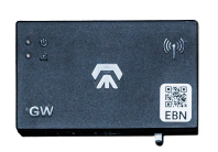
Check for a solid blue LED light in the lower left corner of the digital aggregator.

This indicates power and successful gateway connection.

    Identify signals and outputs

    Choose a suitable signal for utilization
    • A signal that remains in the “on” state for the entire cycle (e.g. “chuck clamp closed” signal).
    • A signal that changes states 1+ times during production (e.g. the control signal for a solenoid on a machine with pneumatic or hydraulic components that fire multiple times per cycle).
    • An external sensor (e.g. proximity switch, light curtain, or line beam sensor) if your machine does not have a suitable signal to represent ongoing production.
    Connecting a dedicated sensor directly to the digital aggregator? You'll need to add a dummy load since the digital aggregator does not source or sink current at the input.
    Locate the signal in your machine
    • Go to the page that lists “Machine I/O” or “Outputs” in your machine schematic or wiring diagram.
    • Find the name corresponding to your chosen signal.
    • Note the output or wire label code and the module label code.
    • Use the codes to locate the module and the output or signal wire in your machine panel.
    Identify nearby power outputs
    It is usually best to find existing 24V and 0V or ground outputs on the same module as the selected signal.
    • Identify a +24V (or +12V if applicable) power output on your machine.
    • Identify a 0V ground output (usually different than the chassis or earth ground).
    • Refer to the same page on the schematic along with the page for the machine DC power supply to confirm the appropriate outputs if you are not sure.
    • Place the digital aggregator near the relevant outputs if you haven’t already done so.

    Connect to your machine

    Connect to power
    • Cut two insulated wires and strip the ends. They should be long enough to connect the power outputs to the digital aggregator.
    • Use one wire to connect the +24V output to the corresponding screw post input on the digital aggregator (the outermost of the three-pin connector).
    • Use the other wire to connect the 0V to the innermost screw post of the same connector.
    • Leave the middle screw post empty.
    • If successfully connected, the rightmost LED should light up when the machine is powered on and +24V power is available.
    Connect to the chosen signal
    The signal will be connected with a single wire.
    • If capturing an existing signal, simply slip the new wire into the output alongside the existing one.
      Tight fit? You may need to remove the existing wire, twist the new one around it, and then reinsert it.
    • If using an empty output, insert the new wire as normal. The wire can then be screwed into the digital aggregator’s input.

    COMPLETE CONFIGURATION

    Set up your machine in the Amper app
    Utilization must be set up first before any cycle count add ons
    • Go to https://app.amper.xyz (or click "complete configuration" below).
    • Go to Settings > Hardware Screen if you're not automatically directed to the instructions.
    • Click "new machine" to begin configuration. The app will guide you through entering your machine and utilization information.
    • Click the “notify us” button at the top right of the page to tell us your machines are ready for calibration.
      Only see a “reconfigure” button? Click it and it will change to “notify us.” Click it again and you’re ready to go.
    Sit back

    Once you submit your machine configuration info, our team will begin tuning your machines and setting up your dashboard. This typically takes 1 week for pilots and 14-21 days for larger full deployments.